ZB4BS844
red Ø40 Emergency stop,switching off head Ø22 trigger and latching turn release
- Range of product
- Harmony XB4
- Product or component type
- Head for emergency switching off push-button
- Device short name
- ZB4
- Bezel material
- Chromium plated metal
- Mounting diameter
- 22 mm
- Sale per indivisible quantity
- 1
- Shape of signaling unit head
- Round
- Type of operator
- Trigger action and mechanical latching
- Reset
- Turn to release
- Operator profile
- Red mushroom Ø 40 mm unmarked
- Head type
- Standard
- CAD overall width
- 40 mm
- CAD overall height
- 40 mm
- CAD overall depth
- 57 mm
- Product weight
- 0.073 kg
- Mechanical durability
- 300000 cycles
- Electrical composition code
- C15 for 1 contacts using single blocks in front mounting
C11 for 3 contacts using single blocks in front mounting
C7 for 4 contacts using single blocks in front mounting
C8 for 4 contacts using single and double blocks in front mounting
C10 for 4 contacts using single and double blocks in front mounting
- Protective treatment
- TH
- Ambient air temperature for storage
- -40...70 °C
- Ambient air temperature for operation
- -40...70 °C
- Electrical shock protection class
- Class I conforming to IEC 61140
- IP degree of protection
- IP69
IP66 conforming to IEC 60529
IP69K - NEMA degree of protection
- NEMA 12
NEMA 13
NEMA 4
NEMA 4X - IK degree of protection
- IK06 conforming to IEC 50102
- Standards
- EN/IEC 60204-1
EN/IEC 60947-1
EN/IEC 60947-5-1
EN/IEC 60947-5-4
EN/IEC 60947-5-5
EN/ISO 13850
IEC 60364-5-53
JIS C 4520
UL 508
GB 14048.5
CSA C22.2 No 14 - Product certifications
- BV
CSA
DNV
GL
LROS (Lloyds register of shipping)
RINA
UL listed - Vibration resistance
- 5 gn (f = 2...500 Hz) conforming to IEC 60068-2-6
- Shock resistance
- 30 gn (duration = 18 ms) for half sine wave acceleration conforming to IEC 60068-2-27
50 gn (duration = 11 ms) for half sine wave acceleration conforming to IEC 60068-2-27
- Sustainable offer status
- Green Premium product
- RoHS (date code: YYWW)
- Schneider Electric declaration of conformity
- REACh
- Reference not containing SVHC above the threshold
- Product environmental profile
- Product Environmental Profile
- Product end of life instructions
- Need no specific recycling operations
- Warranty period
- 18 months 18 months
Frequently Asked Questions and Answers
- CAD file for XY2SB.
Goals and Symptoms CAD file for XY2SB. Causes and Fixes Select attachment Legacy KB System (APS) Data: RESL203137 V1.0, Originally authored by LaBe on 08/19/2010, Last Edited by LaBe on 08/19/2010 Related ranges: Preventa XY2 SB
Read more - What is the RAL-color of a XY2SB714 ?
Goals and Symptoms What is the RAL-color of a XY2SB714 ? Facts and Changes XY2SB714 XY2SB RAL Causes and Fixes The RAL is orange 2008. Legacy KB System (APS) Data: RESL171519 V2.0, Originally authored by ViRe on 07/24/2007, Last Edited by JeLe on 07/26/2013 Related ranges: Preventa XY2 SB
Read more - What are the details for the heat dissipation for the Preventa XPSAC and XPSECME safety modules?
Criterion for relay contacts to be worn out electrically is contact resistance is >= 100 mOhm. Given two contacts with 100 mOhm each in line and the thermal sum current of 10,5 A distributed over 3 channels in case of XPSAC gives a maximum heat dissipation of 7,35 W in the output channels of the XPSAC. Given two contacts with 100 mOhm each in line and the thermal sum current of 12 A distributed over 6 channels in case of XPSECME gives a maximum heat dissipation 4,8 W in the output channels of the XPSECME...
Read more - Preventa XY2C - Dimensions of the xy2cz402 turnbuckle
Find attached dimensions of the XY2CZ402 turnbuckle. XY2CZ402 dimensions.pdf
Read more - Where can we find wiring and mounting data for the XPSAK Preventa safety relays?
See the attached instruction sheet. XPSAK instructions.pdf
Read more
Dimensions Drawings
Mounting and Clearance
Connection by Screw Clamp Terminals or Plug-in Connectors or on Printed Circuit Board | Connection by Faston Connectors |
|
|
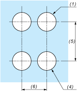
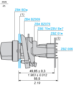
(1) Diameter on finished panel or support (2) 40 mm min. / 1.57 in. min. (3) 30 mm min. / 1.18 in. min. (4) Ø 22.5 mm / 0.89 in. recommended (Ø 22.3 mm 0+0.4 / 0.88 in. 0+0.016) (5) 45 mm min. / 1.78 in. min. (6) 32 mm min. / 1.26 in. min. | |
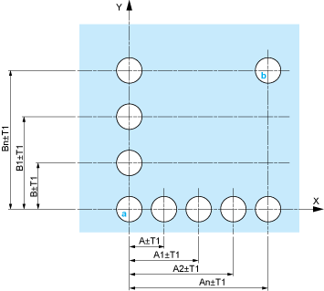
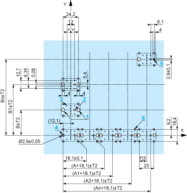
Dimensions in mm
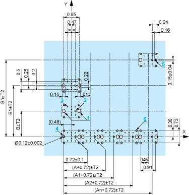
Dimensions in in.
The cumulative tolerance must not exceed 0.3Â mm / 0.012Â in: T1 + T2 = 0.3Â mm max.
Minimum thickness of circuit board: 1.6Â mm / 0.06Â in.
Cut-out diameter: 22.4 mm ± 0.1 / 0.88 in. ± 0.004
Orientation of body/fixing collar ZB4 BZ009: ± 2°30’ (excluding cut-outs marked a and b).
Tightening torque of screws ZBZÂ 006: 0.6Â N.m (5.3Â lbf.in) max.
Allow for one ZB4Â BZ079 fixing collar/pillar and its fixing screws:
every 90Â mm / 3.54Â in. horizontally (X), and 120Â mm / 4.72Â in. vertically (Y).
with each selector switch head (ZB4 BD•, ZB4 BJ•, ZB4 BG•).
The fixing centers marked a and b are diagonally opposed and must align with those marked 4 and 5.
1 2 elongated holes for ZBZÂ 006 screw access
2 1 hole Ø 2.4 mm ± 0.05 / 0.09 in. ± 0.002 for centring adapter ZBZ 01•
3 8 × Ø 1.2 mm / 0.05 in. holes
4 1 hole Ø 2.9 mm ± 0.05 / 0.11 in. ± 0.002, for aligning the printed circuit board (with cut-out marked a)
5 1 elongated hole for aligning the printed circuit board (with cut-out marked b)
6 4 holes Ø 2.4 mm / 0.09 in. for clipping in adapter ZBZ 01•
Dimensions An + 18.1 relate to the Ø 2.4 mm ± 0.05 / 0.09 in. ± 0.002 holes for centring adapter ZBZ 01•.
Technical Description


1 N/O

1 N/C

1 N/O + N/C or 1 N/O + N/O or 1 N/C + N/C

Single contact

Double contact

Light block

Possible location


