Dimensions
Ø in mm | Ø in in. | |
|---|---|---|
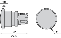
ZB4BC• | 40 | 1.57 |
ZB4BR• | 60 | 2.36 |
There is no answer for this question.
The pushbuttons and LEDs are IP66 The selector switches are IP69K. The IP rating can be improved by adding covers, which increases the protection index to IP69K. Push button single boots ZBP Double-Heared push button boots ZBW or ZBA7 Mushroom headed Buttons ZBZ
Read more
For Harmony XB4/XB5 22 diameter control and signalling units, whether: LED lamps, incandescent lamps, neon lamps, there are part numbers with BA9s base fitting:
Read more
Issue: Clarify the 22mm operator IP rating Product Line: Harmony XB4/XB5 22mm push button Environment: US Product Cause: Product Specification Resolution: As of 2017, all of the XB4 and XB5 push buttons are rated IP66, IP67, IP69, and IP69K
Read more
Issue: Difference between trigger action and non-trigger action pushbuttons Product Line: Harmony XB4/XB5 Environment: US product Cause: What is the difference in size and actuation of trigger action pushbuttons Resolution: Trigger action pushbuttons are impossible to partially engage the contacts. The trigger action causes the operator to snap over from one state to the other once engaged past a point of no return. For safety applications and emergency off/stop applications, this is the prefe...
Read more

Ø in mm | Ø in in. | |
|---|---|---|
ZB4BC• | 40 | 1.57 |
ZB4BR• | 60 | 2.36 |
Connection by Screw Clamp Terminals or Plug-in Connectors or on Printed Circuit Board | Connection by Faston Connectors |
|
|
(1) Diameter on finished panel or support (2) 40 mm min. / 1.57 in. min. (3) 30 mm min. / 1.18 in. min. (4) Ø 22.5 mm / 0.89 in. recommended (Ø 22.3 mm 0+0.4 / 0.88 in. 0+0.016) (5) 45 mm min. / 1.78 in. min. (6) 32 mm min. / 1.26 in. min. | |
Dimensions in mm
Dimensions in in.
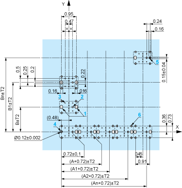
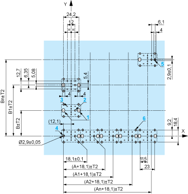
The cumulative tolerance must not exceed 0.3Â mm / 0.012Â in: T1 + T2 = 0.3Â mm max.
Minimum thickness of circuit board: 1.6Â mm / 0.06Â in.
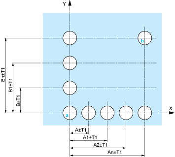
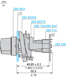
Cut-out diameter: 22.4 mm ± 0.1 / 0.88 in. ± 0.004
Orientation of body/fixing collar ZB4 BZ009: ± 2°30’ (excluding cut-outs marked a and b).
Tightening torque of screws ZBZÂ 006: 0.6Â N.m (5.3Â lbf.in) max.
Allow for one ZB4Â BZ079 fixing collar/pillar and its fixing screws:
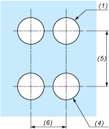
every 90Â mm / 3.54Â in. horizontally (X), and 120Â mm / 4.72Â in. vertically (Y).
with each selector switch head (ZB4 BD•, ZB4 BJ•, ZB4 BG•).
The fixing centers marked a and b are diagonally opposed and must align with those marked 4 and 5.
1 2 elongated holes for ZBZÂ 006 screw access
2 1 hole Ø 2.4 mm ± 0.05 / 0.09 in. ± 0.002 for centring adapter ZBZ 01•
3 8 × Ø 1.2 mm / 0.05 in. holes
4 1 hole Ø 2.9 mm ± 0.05 / 0.11 in. ± 0.002, for aligning the printed circuit board (with cut-out marked a)
5 1 elongated hole for aligning the printed circuit board (with cut-out marked b)
6 4 holes Ø 2.4 mm / 0.09 in. for clipping in adapter ZBZ 01•
Dimensions An + 18.1 relate to the Ø 2.4 mm ± 0.05 / 0.09 in. ± 0.002 holes for centring adapter ZBZ 01•.

1 N/O

1 N/C

1 N/O + N/C or 1 N/O + N/O or 1 N/C + N/C

Single contact

Double contact

Light block

Possible location