TM3DQ32TK
module TM3 - 32 outputs transistor PNP HE10
- Range of product
- Modicon TM3
- Product or component type
- Discrete output module
- Range compatibility
- Modicon M221
Modicon M241
Modicon M251 - Discrete output type
- Transistor
- Discrete output number
- 32
- Discrete output logic
- Positive logic (source)
- Discrete output voltage
- 24 V DC for transistor output
- Discrete output current
- 100 mA for transistor output
- Discrete I/O number
- 32
- Current consumption
- 5 mA at 5 V DC via bus connector at state off
0 mA at 24 V DC via bus connector at state off
25 mA at 5 V DC via bus connector at state on
40 mA at 24 V DC via bus connector at state on - Response time
- 450 µs for turn-on
450 µs for turn-off - Leakage current
- 0.1 mA for transistor output
- Voltage drop
- 0.4 V
- Tungsten load
- 1.2 W for transistor output
- Local signalling
- 1 LED per channel green for output status
- Electrical connection
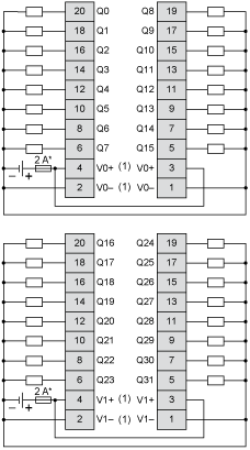
- HE-10 connector for outputs
- Insulation
- 500 V AC between output and internal logic
Non-insulated between outputs - Marking
- CE
- Mounting support
- Top hat type TH35-15 rail conforming to IEC 60715
Top hat type TH35-7.5 rail conforming to IEC 60715
Plate or panel with fixing kit - Height
- 90 mm
- Depth
- 81.3 mm
- Width
- 33.5 mm
- Product weight
- 0.112 kg
- Standards
- EN/IEC 61131-2
EN/IEC 61010-2-201 - Product certifications
- C-Tick
cULus - Resistance to electrostatic discharge
- 4 kV (on contact) conforming to EN/IEC 61000-4-2
8 kV (in air) conforming to EN/IEC 61000-4-2 - Resistance to electromagnetic fields
- 10 V/m at 80 MHz...1 GHz conforming to EN/IEC 61000-4-3
3 V/m at 1.4 GHz...2 GHz conforming to EN/IEC 61000-4-3
1 V/m at 2 GHz...3 GHz conforming to EN/IEC 61000-4-3 - Resistance to magnetic fields
- 30 A/m 50/60 Hz conforming to EN/IEC 61000-4-8
- Resistance to fast transients
- 1 kV for I/O conforming to EN/IEC 61000-4-4
- Surge withstand
- 1 kV for I/O (DC) in common mode conforming to EN/IEC 61000-4-5
- Resistance to conducted disturbances
- 10 Vrms at 0.15...80 MHz conforming to EN/IEC 61000-4-6
3 Vrms at spot frequency (2, 3, 4, 6.2, 8.2, 12.6, 16.5, 18.8, 22, 25 MHz) conforming to Marine specification (LR, ABS, DNV, GL) - Electromagnetic emission
- Radiated emissions, test level: 40 dBμV/m QP with class A, condition of test: 10 m (radio frequency: 30...230 MHz) conforming to EN/IEC 55011
Radiated emissions, test level: 47 dBμV/m QP with class A, condition of test: 10 m (radio frequency: 230...1000 MHz) conforming to EN/IEC 55011 - Ambient air temperature for operation
- -10...55 °C for horizontal installation
-10...35 °C for vertical installation - Ambient air temperature for storage
- -25...70 °C
- Relative humidity
- 10...95 % without condensation in operation
10...95 % without condensation in storage - IP degree of protection
- IP20 with protective cover in place
- Pollution degree
- 2
- Operating altitude
- 0...2000 m
- Storage altitude
- 0...3000 m
- Vibration resistance
- 3.5 mm (vibration frequency: 5...8.4 Hz) on DIN rail
3 gn (vibration frequency: 8.4...150 Hz) on DIN rail
3.5 mm (vibration frequency: 5...8.4 Hz) on panel
3 gn (vibration frequency: 8.4...150 Hz) on panel - Shock resistance
- 15 gn (test wave duration:11 ms)
- Sustainable offer status
- Green Premium product
- RoHS (date code: YYWW)
- Schneider Electric declaration of conformity
- REACh
- Reference not containing SVHC above the threshold
- Product environmental profile
- Product Environmental Profile
- Product end of life instructions
- End of Life Information
Frequently Asked Questions and Answers
- Can I disable a TM3 module in SoMachine?
Issue: Set the TM3 module as optional in SoMachine Product Line: Modicon TM3 Resolution: It's possible to set a TM3 module as optional in SoMachine. This will allow you to run your program without faulting the TM3 bus even if the TM3 module is not physically present on the rack. See attached screenashot for how to do that in SoMachine. TM3.png
Read more - What is the maximum number of expansion modules for M221 controllers
Local I/O Maximum configuration: 7 Modicon TM3 expansion modules associated with an M221 logic controller. Depending on the expansion module references, there may be fewer than 7. Remote I/O Maximum configuration: 14 Modicon TM3 expansion modules (7 local modules + 7 remote modules) with the Modicon TM3 bus expansion system (transmitter module and receiver module is not included in the maximum number of modules). TM3 expansion modules are powered by logic controllers via the bus connector on the side ...
Read more - Reverse PID mode in Modicon M241/M251
There is no input to select between direct/inverse direction at the PID function block from the Util library. The FB_PID function block (Toolbox library) is from Schneider and has additional features. With FB_PID function block from the Toolbox library in SoMachine to change the regulation direction user can use negative P-factor (i_rKp) The basic PID function must remain the same.
Read more - Can we use 800 IOs with Modicon m580 Safety System without impact TUV certification
There is no issue to use 800 series IOs without any impact on TÜV certificate on a M580 Safety configuration. As a general rule, all of Remote Distributed equipments on Ethernet allowed in M580 system could be considered as “non-interfering” for Safety M580 modules. However, of course, 800 series IOs data are not supposed to be used to perform safety functions.
Read more - Video: Setting Persistent Variables with the Modicon M221 in SoMachine Basic
The video demonstrates how to set up persistent variables and save them in the memory words of SoMachine Basic.
Read more
Dimensions Drawings
Mounting and Clearance


Connections and Schema


