
Dimensions
Rear Mounting

e
support panel thickness 0.5 to 5.5 mm / 0.02 to 0.22 in in.
a | b | c | D1 | ||||
|---|---|---|---|---|---|---|---|
mm | in. | mm | in. | mm | in. | mm | in. |
100 | 3.94 | 88 | 3.46 | 88 | 3.46 | 5.4 | 0.21 |

a | b | c | D1 | ||||
|---|---|---|---|---|---|---|---|
mm | in. | mm | in. | mm | in. | mm | in. |
100 | 3.94 | 88 | 3.46 | 88 | 3.46 | 5.4 | 0.21 |

D2 | D3 | G1 | |||
|---|---|---|---|---|---|
mm | in. | mm | in. | mm | in. |
6 | 0.24 | 13 | 0.51 | 68 | 2.68 |
Select the number of poles according to the product characteristics


Select the number of poles according to the product characteristics
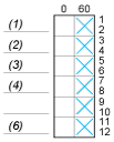
 Contact closed
 Contact closed in 2 positions and maintained between the 2 positions
 Sealed assembly for auto-maintain control
 Overlapping contacts
 Spring return position: for a switching angle of 90°, spring return is over 30° after the last position (for a maximum of 3 simultaneous contacts).
Example:
