Recommended Wiring Diagram
3-Phase Power Supply
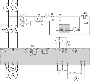
Q2:
GV2Â L rated at twice the nominal primary current of T1
S1, S2:
XB4Â B or XB5Â A pushbuttons
T1:
100Â VA transformer 220Â V secondary
(1)
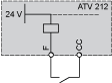
Fault relay contacts for remote signalling of the drive status
(2)
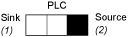
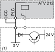
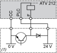
Connection of the common for the logic inputs depends on the positioning of the switch (Source, PLC, Sink)
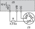
(3)
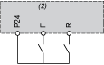
Reference potentiometer SZ1RV1202
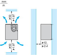
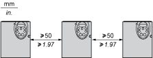
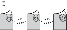
NOTE: All terminals are located at the bottom of the drive. Install interference suppressors on all inductive circuits near the drive or connected on the same circuit, such as relays, contactors, solenoid valves, fluorescent lighting, etc.
Switches (Factory Settings)
Voltage/current selection for analog I/O (VIA and VIB)

Voltage/current selection for analog I/O (FM)

Selection of logic type
Other Possible Wiring Diagrams
Logic Inputs According to the Position of the Logic Type Switch
“Source†position
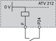
“Sink†position
“PLC†position with PLC transistor outputs |
| 
|
2-wire control
(2)
ATVÂ 212 control terminals
3-wire control

(2)
ATVÂ 212 control terminals
PTC probe
(2)
ATVÂ 212 control terminals
Analog Inputs
Voltage analog inputs
External +10Â V |
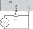
(2) ATV 212 control terminals (4) Speed reference potentiometer 2.2 to 10 kΩ | 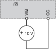
(2) ATVÂ 212 control terminals |
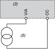
Analog input configured for current: 0-20Â mA, 4-20Â mA, X-YÂ mA
(2)
ATVÂ 212 control terminals
(5)
Source 0-20Â mA, 4-20Â mA, X-YÂ mA
Analog input VIA configured as positive logic input (“Source†position)
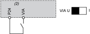
(2)
ATVÂ 212 control terminals
Analog input VIA configured as negative logic input (“Sink†position)
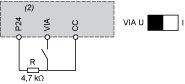
(2)
ATVÂ 212 control terminals