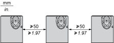
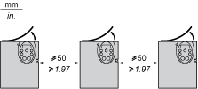
Dimensions
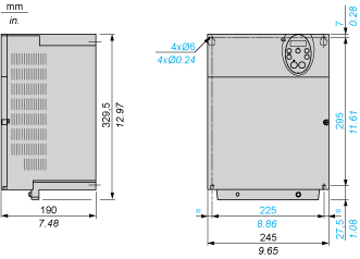
Plate for EMC mounting (supplied with the drive)
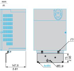
(1)
2 x M5 screws
Issue: Do you offer a din rail mounting kit for a ATV212HD15N4? Product Line: ATV212 Environment: Altivar 212H075M3X...U22M3X, Altivar 212H075N4...U22N4 Cause: Product Selection & Services Resolution: No there is no din rail mounting kit for the ATV212HD15N4? DIN Rail Mounting Kit part number VW3A31852. For installation on 35 mm wide DIN rail available only for: Altivar 212H075M3X...U22M3X Altivar 212H075N4...U22N4
Read more
Issue: Can an ATV212 drive's programming be saved to the HMI keypad (VW3A1101) and transferred to another ATV212? Product Line: Altivar 212 Environment: All Cause: N/A Resolution: No, the ATV212's programming cannot be saved to any of the keypads available. Programming can be saved by any of three methods: - in the drive by setting parameter tYP = 7 - in the Multiloader tool - by using SoMove software, downloading the ATV212 DTM File, and using the TCSMCNAM3M002P - SoMove cable
Read more
Issue: On an ATV212, what does a flashing E17 code mean? Product Line: ATV212 Environment: Flashing E17 Cause: Resolution: This code indicates that a keypad button has been depressed for more than 20 seconds. Release the depressed button to clear the fault. Attempt to free a stuck button by repeatedly pressing/releasing all keypad buttons. If these do not clear the fault, replace the drive.
Read more
Issue: Can the ATV21, 212, or S-Flex drives communicate using ethernet IP protocol? Product Line: Altivar 21 / ATV21 Altivar 212 / ATV212 S-Flex enclosed drives Environment: All part numbers, all serial numbers Cause: N/A Resolution: No, Ethernet IP is not available with the ATV21 or ATV212 drive unless a gateway is used to convert ethernet ip to a standard protocol support by the ATV212 drive line such as modbus RTU.
Read more
Issue: What causes E-17 fault on an ATV21 / ATV212 series drive? Product Line: ATV21 and ATV212 series drives Environment: All models, All serial numbers Cause: Clarification of fault code needed Resolution: E-17 is displayed on the ATV21 / ATV212 series drives when a button on the keypad is held down for more than 20 seconds. If no button is being held down, then this could be an electrical problem with the switch were it is making contact when it is not being pressed, or possibly a problem wit...
Read more

Plate for EMC mounting (supplied with the drive)
Depending on the conditions in which the drive is to be used, its installation will require certain precautions and the use of appropriate accessories.
Install the unit vertically:
Do not place it close to heating elements.
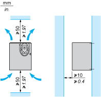
Leave sufficient free space to ensure that the air required for cooling purposes can circulate from bottom to the top of the unit.
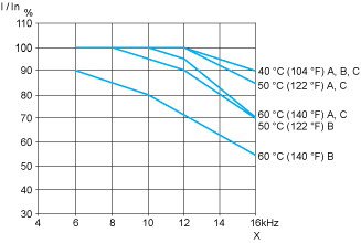
Type A mounting
Type B mounting
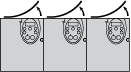
Type C mounting
By removing the protective blanking cover from the top of the drive, the degree of protection for the drive becomes IP21. The protective blanking cover may vary according to the drive model, see opposite.
To help ensure proper air circulation in the drive:
Fit ventilation grilles.
Check that there is sufficient ventilation. If there is not, install a forced ventilation unit with a filter. The openings and/or fans must provide a flow rate at least equal to that of the drive fans (refer to the product characteristics). 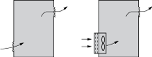
Use special filters with UL Type 12/IP54 protection.
Remove the blanking cover from the top of the drive.
The drive must be mounted in a dust and damp proof enclosure in certain environmental conditions, such as dust, corrosive gases, high humidity with risk of condensation and dripping water, splashing liquid, etc.This enables the drive to be used in an enclosure where the maximum internal temperature reaches 50°C.
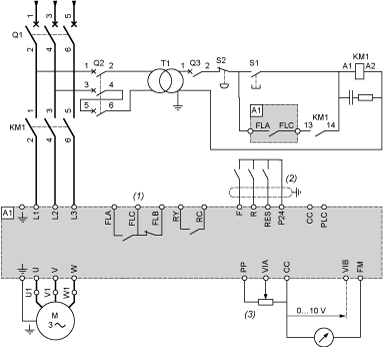
NOTE: All terminals are located at the bottom of the drive. Install interference suppressors on all inductive circuits near the drive or connected on the same circuit, such as relays, contactors, solenoid valves, fluorescent lighting, etc.
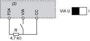
Voltage/current selection for analog I/O (VIA and VIB)

Voltage/current selection for analog I/O (FM)

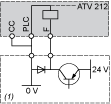
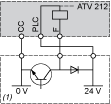
Selection of logic type
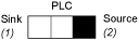
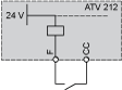
“Source†position
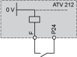
“Sink†position
“PLC†position with PLC transistor outputs | |
(1) PLC |
(1) PLC |
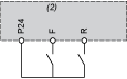
2-wire control
3-wire control

PTC probe
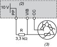
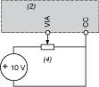
Voltage analog inputs
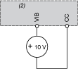
External +10Â V | |
(2) ATV 212 control terminals (4) Speed reference potentiometer 2.2 to 10 kΩ |
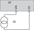
(2) ATVÂ 212 control terminals |
Analog input configured for current: 0-20Â mA, 4-20Â mA, X-YÂ mA
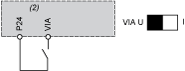
Analog input VIA configured as positive logic input (“Source†position)
Analog input VIA configured as negative logic input (“Sink†position)
The derating curves for the drive nominal current (In) depend on the temperature, the switching frequency and the mounting type (A, B or C).
For intermediate temperatures (45°C for example), interpolate between 2 curves.