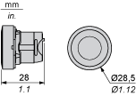
ZB5AA334
white flush pushbutton head Ø22 spring return 'up arrow'
- Range of product
- Harmony XALF
Harmony XB5 - Product or component type
- Head for non-illuminated push-button
- Device short name
- ZB5
- Bezel material
- Plastic
- Mounting diameter
- 22 mm
- Head type
- Standard
- Sale per indivisible quantity
- 1
- Shape of signaling unit head
- Round
- Type of operator
- Spring return
- Operator profile
- White flush, black up arrow
- CAD overall width
- 29 mm
- CAD overall height
- 29 mm
- CAD overall depth
- 28 mm
- Product weight
- 0.018 kg
- Mechanical durability
- 10000000 cycles
- Station name
- XALD 1...5 cut-outs
XALK 2...5 cut-outs - Electrical composition code
- C1 for <= 9 contacts using single blocks in front mounting
C2 for <= 9 contacts using single and double blocks in front mounting
C11 for <= 3 contacts using single blocks in front mounting
C15 for 1 contacts using single blocks in front mounting
SF1 for <= 3 contacts using single blocks in front mounting
SR1 for <= 3 contacts using single blocks in rear mounting
- Protective treatment
- TH
- Ambient air temperature for storage
- -40...70 °C
- Ambient air temperature for operation
- -40...70 °C
- Overvoltage category
- Class II conforming to IEC 60536
- IP degree of protection
- IP69
IP67
IP66 conforming to IEC 60529
IP69K - NEMA degree of protection
- NEMA 13
NEMA 4X - Resistance to high pressure washer
- 7000000 Pa at 55 °C,distance: 0.1 m
- IK degree of protection
- IK03 conforming to IEC 50102
- Standards
- EN/IEC 60947-1
EN/IEC 60947-5-1
EN/IEC 60947-5-4
JIS C 4520
UL 508
CSA C22.2 No 14 - Product certifications
- BV
CSA
DNV
GL
LROS (Lloyds register of shipping)
RINA
UL listed - Shock resistance
- 30 gn (duration = 18 ms) for half sine wave acceleration conforming to IEC 60068-2-27
50 gn (duration = 11 ms) for half sine wave acceleration conforming to IEC 60068-2-27 - Vibration resistance
- 5 gn (f = 2...500 Hz) conforming to IEC 60068-2-6
- Warranty period
- 18 months
Frequently Asked Questions and Answers
- Is the ZB4BP3 harmony pushbutton IP rated?
Yes the ZB4BP3 is rated to IP69K.
Read more - Video: Resetting a Harmony XB5R Wireless Push Button Receiver
Issue: Reset the Wireless Receiver on the XB5R Wireless Push Button Product Line: Push Button and Operator Interface Environment: XB5R Wireless Push Buttons Resolution: 1. Hold down both buttons simultaneously 2. Wait for all of the lights to start flashing 3. Press both buttons down again until they go solid 4. Remove your fingers 5. Your device is now reset
Read more - What code is a Harmony flashing LED light block 240vac?
ZBV18M1 = White ZBV18M3 = Green ZBV18M4 = Red ZBV18M5 = Yellow ZBV18M6 = Blue
Read more - Video: How to configure Harmony XVU Tower Light color and illumination settings
Product Line: XVU Tower/Stack Light XVUC29 Resolution: On page three of three in the included instructions you will find two boxes.One labled Dial \'A\' and one labeled Dial \'B.\' Using these tables, select the features that you want. Then set the dials marked \'A\' and \'B\' on the top of your XVU unit to match your requirements. To change the dials you will need to use a small, flathead screwdriver. 157.198.234.35_Scan_to_Desktop_10-18-2016_08-22-59.pdf
Read more - Video: Removing Contacts from a Harmony 9001 30mm Operator
Product Line: 9001K and 9001SK Operators Resolution: Make sure no nearby components are powered during the disassemble process. 1. Use a small, flathead screw driver and loosen the mounting screw on the contact 2. Dettach the contact from the operator base
Read more
Dimensions Drawings

Mounting and Clearance

Connections | a in mm | a in in. | b in mm | b in in. |
|---|---|---|---|---|
By screw clamp terminals or plug-in connector | 40 | 1.57 | 30 | 1.18 |
By Faston connectors | 45 | 1.77 | 32 | 1.26 |
On printed circuit board | 30 | 1.18 | 30 | 1.18 |
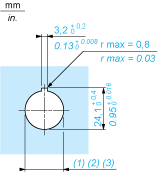
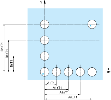
Dimensions in mm
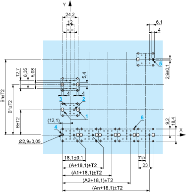
Dimensions in in.
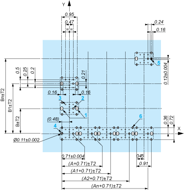
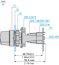
The cumulative tolerance must not exceed 0.3Â mm / 0.012Â in.: T1 + T2 = 0.3Â mm max.
Minimum thickness of circuit board: 1.6Â mm / 0.06Â in.
Cut-out diameter: 22.4 mm ± 0.1 / 0.88 in. ± 0.004
Orientation of body/fixing collar ZB5AZ009: ± 2°30’ (excluding cut-outs marked a and b).
Tightening torque of screws ZBZ006: 0.6Â N.m (5.3Â lbf.in) max.
Allow for one ZB5AZ079 fixing collar/pillar and its fixing screws:
every 90Â mm / 3.54Â in. horizontally (X), and 120Â mm / 4.72Â in. vertically (Y).
with each selector switch head (ZB5AD•, ZB5AJ•, ZB5AG•).
The fixing centers marked a and b are diagonally opposed and must align with those marked 4 and 5.
1 2 elongated holes for ZBZ006 screw access
2 1 hole Ø 2.4 mm ± 0.05 / 0.09 in. ± 0.002 for centring adapter ZBZ01•
3 8 × Ø 1.2 mm / 0.05 in. holes
4 1 hole Ø 2.9 mm ± 0.05 / 0.11 in. ± 0.002, for aligning the printed circuit board (with cut-out marked a)
5 1 elongated hole for aligning the printed circuit board (with cut-out marked b)
6 4 holes Ø 2.4 mm / 0.09 in. for clipping in adapter ZBZ01•
Dimensions An + 18.1 relate to the Ø 2.4 mm ± 0.05 / 0.09 in. ± 0.002 holes for centring adapter ZBZ01•.
Technical Description


1 N/O

1 N/C

1 N/O + N/C or 1 N/O + N/O or 1 N/C + N/C

Single contact

Double contact

Light block

Possible location


