ATV212H075N4

$1,039.39
Special Order-Generally ships in 14 to 21 Business Days
SKU
ATV212H075N4

variable speed drive ATV212 - 0.75kW - 1hp - 480V - 3ph - EMC - IP21

Main
Range of product
Altivar 212
Product or component type
Variable speed drive
Device short name
ATV212
Product destination
Asynchronous motors
Product specific application
Pumps and fans in HVAC
Assembly style
With heat sink
Network number of phases
3 phases
Motor power kW
0.75 kW
Motor power hp
1 hp
[Us] rated supply voltage
380...480 V - 15...10 %
Supply voltage limits
323...528 V
Supply frequency
50...60 Hz - 5...5 %
Network frequency
47.5...63 Hz
EMC filter
Class C2 EMC filter integrated
Line current
1.4 A 480 V

1.7 A 380 V
Complementary
Analogue output type
Switch-configurable voltage FM 0...10 V DC 7620 Ohm 10 bits

Switch-configurable current FM 0...20 mA 970 Ohm 10 bits
Discrete output number
2
Discrete output type
Configurable relay logic FLA, FLC NO 100000 cycles

Configurable relay logic FLB, FLC NC 100000 cycles

Configurable relay logic RY, RC NO 100000 cycles
Minimum switching current
3 mA 24 V DC configurable relay logic
Maximum switching current
5 A 250 V AC resistive cos phi = 1 L/R = 0 ms FL, R

5 A 30 V DC resistive cos phi = 1 L/R = 0 ms FL, R

2 A 250 V AC inductive cos phi = 0.4 L/R = 7 ms FL, R

2 A 30 V DC inductive cos phi = 0.4 L/R = 7 ms FL, R
Discrete input type
Programmable F 24 V DC level 1 PLC 4700 Ohm

Programmable R 24 V DC level 1 PLC 4700 Ohm

Programmable RES 24 V DC level 1 PLC 4700 Ohm
Discrete input logic
Positive logic (source) F, R, RES <= 5 V >= 11 V

Negative logic (sink) F, R, RES >= 16 V <= 10 V
Acceleration and deceleration ramps
Automatic based on the load

Linear adjustable separately from 0.01 to 3200 s
Braking to standstill
By DC injection
Protection type
Motor phase break motor

Break on the control circuit drive

Thermal power stage drive

Overvoltages on the DC bus drive

Against exceeding limit speed drive

Against input phase loss drive

With PTC probes motor

Input phase breaks drive

Line supply overvoltage and undervoltage drive

Line supply undervoltage drive

Overcurrent between output phases and earth drive

Overheating protection drive

Short-circuit between motor phases drive

Thermal protection motor
Dielectric strength
3535 V DC between earth and power terminals

5092 V DC between control and power terminals
Insulation resistance
>= 1 MOhm 500 V DC for 1 minute
Frequency resolution
0.024/50 Hz analog input

0.1 Hz display unit
Communication port protocol
APOGEE FLN

BACnet

LonWorks

METASYS N2

Modbus
Connector type
1 RJ45

1 open style
Physical interface
2-wire RS 485
Transmission frame
RTU
Transmission rate
9600 bps or 19200 bps
Data format
8 bits, 1 stop, odd even or no configurable parity
Type of polarization
No impedance
Number of addresses
1...247
Communication service
Monitoring inhibitable

Read device identification (43)

Read holding registers (03) 2 words maximum

Time out setting from 0.1 to 100 s

Write multiple registers (16) 2 words maximum

Write single register (06)
Option card
Communication card LonWorks
Operating position
Vertical +/- 10 degree
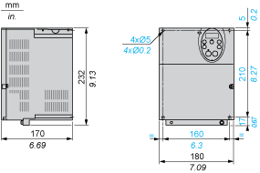
Width
107 mm
Height
143 mm
Depth
150 mm
Product weight
2 kg
Power dissipation in W
55 W
Air flow
19 m3/h
Functionality
Mid
Specific application
HVAC
IP degree of protection
IP21
Discrete and process manufacturing
Building - HVAC : compressor for scroll

Building - HVAC : fan

Building - HVAC : pump
Power range
0.55...1 kW at 380...440 V 3 phases

0.55...1 kW at 480...500 V 3 phases
Motor starter type
Variable speed drive
Apparent power
1.6 kVA 380 V
Prospective line Isc
5 kA
Continuous output current
2.2 A 380 V

2.2 A 460 V
Maximum transient current
2.4 A 60 s
Speed drive output frequency
0.5...200 Hz
Nominal switching frequency
12 kHz
Switching frequency
12...16 kHz with derating factor

6...16 kHz adjustable
Speed range
1...10
Speed accuracy
+/- 10 % of nominal slip 0.2 Tn to Tn
Torque accuracy
+/- 15 %
Transient overtorque
120 % of nominal motor torque +/- 10 % 60 s
Asynchronous motor control profile
Voltage/frequency ratio, 2 points

Voltage/frequency ratio, 5 points

Flux vector control without sensor, standard

Voltage/frequency ratio - Energy Saving, quadratic U/f

Voltage/frequency ratio, automatic IR compensation (U/f + automatic Uo)
Regulation loop
Adjustable PI regulator
Motor slip compensation
Adjustable

Automatic whatever the load

Not available in voltage/frequency ratio motor control
Local signalling
1 LED red DC bus energized
Output voltage
<= power supply voltage
Isolation
Electrical between power and control
Type of cable
IEC cable without mounting kit 1 45 °C copper 90 °C XLPE/EPR

IEC cable without mounting kit 1 45 °C copper 70 °C PVC

UL 508 cable with UL Type 1 kit 3 40 °C copper 75 °C PVC
Electrical connection
Terminal 2.5 mm² AWG 14 VIA, VIB, FM, FLA, FLB, FLC, RY, RC, F, R, RES

Terminal 6 mm² AWG 10 L1/R, L2/S, L3/T
Tightening torque
1.3 N.m 11.5 lb.in L1/R, L2/S, L3/T

0.6 N.m VIA, VIB, FM, FLA, FLB, FLC, RY, RC, F, R, RES
Supply
Internal supply for reference potentiometer (1 to 10 kOhm) 10.5 V DC +/- 5 % <= 10 A overload and short-circuit protection

Internal supply 24 V DC 21...27 V <= 200 A overload and short-circuit protection
Analogue input number
2
Analogue input type
Switch-configurable voltage VIA 0...10 V DC 24 V max 30000 Ohm 10 bits

Configurable voltage VIB 0...10 V DC 24 V max 30000 Ohm 10 bits

Configurable PTC probe VIB 0...6 probes 1500 Ohm

Switch-configurable current VIA 0...20 mA 250 Ohm 10 bits
Sampling duration
2 ms +/- 0.5 ms F discrete

2 ms +/- 0.5 ms R discrete

2 ms +/- 0.5 ms RES discrete

3.5 ms +/- 0.5 ms VIA analog

22 ms +/- 0.5 ms VIB analog
Response time
2 ms +/- 0.5 ms FM analog

7 ms +/- 0.5 ms FLA, FLC discrete

7 ms +/- 0.5 ms FLB, FLC discrete

7 ms +/- 0.5 ms RY, RC discrete
Accuracy
+/- 0.6 % VIA for a temperature variation 60 °C

+/- 0.6 % VIB for a temperature variation 60 °C

+/- 1 % FM for a temperature variation 60 °C
Linearity error
+/- 0.15 % of maximum value input VIA

+/- 0.15 % of maximum value input VIB

+/- 0.2 % output FM
Analogue output number
1
Environment
Electromagnetic compatibility
Conducted radio-frequency immunity test level 3 IEC 61000-4-6

Voltage dips and interruptions immunity test IEC 61000-4-11

1.2/50 µs - 8/20 µs surge immunity test level 3 IEC 61000-4-5

Electrical fast transient/burst immunity test level 4 IEC 61000-4-4

Electrostatic discharge immunity test level 3 IEC 61000-4-2

Radiated radio-frequency electromagnetic field immunity test level 3 IEC 61000-4-3
Pollution degree
2 IEC 61800-5-1
IP degree of protection
IP20 on upper part without blanking plate on cover EN/IEC 61800-5-1

IP20 on upper part without blanking plate on cover EN/IEC 60529

IP21 EN/IEC 61800-5-1

IP21 EN/IEC 60529

IP41 on upper part EN/IEC 61800-5-1

IP41 on upper part EN/IEC 60529
Vibration resistance
1 gn 13...200 Hz EN/IEC 60068-2-8

1.5 mm 3...13 Hz EN/IEC 60068-2-6
Shock resistance
15 gn 11 ms IEC 60068-2-27
Environmental characteristic
Classes 3C1 IEC 60721-3-3

Classes 3S2 IEC 60721-3-3
Noise level
51 dB 86/188/EEC
Operating altitude
1000...3000 m limited to 2000 m for the Corner Grounded distribution network with current derating 1 % per 100 m

<= 1000 m without derating
Relative humidity
5...95 % without condensation IEC 60068-2-3

5...95 % without dripping water IEC 60068-2-3
Ambient air temperature for operation
-10...40 °C without derating

> 40...50 °C with derating factor
Ambient air temperature for storage
-25...70 °C
Standards
EN 55011 class A group 1

EN 61800-3

EN 61800-3 category C2

EN 61800-3 category C3

EN 61800-3 environments 1 category C1

EN 61800-3 environments 1 category C2

EN 61800-3 environments 1 category C3

EN 61800-3 environments 2 category C1

EN 61800-3 environments 2 category C2

EN 61800-3 environments 2 category C3

EN 61800-5-1

IEC 61800-3

IEC 61800-3 category C2

IEC 61800-3 category C3

IEC 61800-3 environments 1 category C1

IEC 61800-3 environments 1 category C2

IEC 61800-3 environments 1 category C3

IEC 61800-3 environments 2 category C1

IEC 61800-3 environments 2 category C2

IEC 61800-3 environments 2 category C3

IEC 61800-5-1

UL Type 1
Product certifications
CSA

C-Tick

NOM 117

UL
Marking
CE
Offer Sustainability
Sustainable offer status
Green Premium product
RoHS (date code: YYWW)
Schneider Electric declaration of conformity
REACh
Reference not containing SVHC above the threshold
Product environmental profile
Product Environmental Profile
Product end of life instructions
Available
Contractual warranty
Warranty period
18 months
Write Your Own Review
You're reviewing:ATV212H075N4

   Frequently Asked Questions and Answers


  • Can an ATV212 drive\'s programming be saved to the HMI keypad (vw3a1101) and transferred to another ATV212?

    Issue: Can an ATV212 drive's programming be saved to the HMI keypad (VW3A1101) and transferred to another ATV212? Product Line: Altivar 212 Environment: All Cause: N/A Resolution: No, the ATV212's programming cannot be saved to any of the keypads available.   Programming can be saved by any of three methods: - in the drive by setting parameter tYP = 7 - in the Multiloader tool - by using SoMove software, downloading the ATV212 DTM File, and using the TCSMCNAM3M002P - SoMove cable
    Read more

  • On an ATV212, what does a flashing E17 code mean?

    Issue:  On an ATV212, what does a flashing E17 code mean? Product Line:  ATV212 Environment:  Flashing E17 Cause:   Resolution: This code indicates that a keypad button has been depressed for more than 20 seconds.  Release the depressed button to clear the fault.  Attempt to free a stuck button by repeatedly pressing/releasing all keypad buttons.  If these do not clear the fault, replace the drive.
    Read more

  • Can the ATV21, 212, or S-Flex drives communicate using ethernet IP protocol?

    Issue: Can the ATV21, 212, or S-Flex drives communicate using ethernet IP protocol? Product Line: Altivar 21 / ATV21 Altivar 212 / ATV212 S-Flex enclosed drives Environment: All part numbers, all serial numbers Cause: N/A Resolution: No, Ethernet IP is not available with the ATV21 or ATV212 drive unless a gateway is used to convert ethernet ip to a standard protocol support by the ATV212 drive line such as modbus RTU.
    Read more

  • What causes E-17 fault on an ATV21 / ATV212 series drive?

    Issue: What causes E-17 fault on an ATV21 / ATV212 series drive? Product Line: ATV21 and ATV212 series drives Environment: All models, All serial numbers Cause: Clarification of fault code needed Resolution: E-17 is displayed on the ATV21 / ATV212 series drives when a button on the keypad is held down for more than 20 seconds.  If no button is being held down, then this could be an electrical problem with the switch were it is making contact when it is not being pressed, or possibly a problem wit...
    Read more

  • Video: How can you program the ATV212 drive to run in local mode?

    Issue: How can you program the ATV212 drive to run from in local mode (face of the drive)? Product Line: Altivar ATV21 and ATV212 Environment: All Cause: Needs to use the run/ stop buttons on the face of the drive. Resolution: Programming as follows using the integral display If you would like to be able to switch back and forth between local mode and remote mode, the LOC/REM button can be used. This button has an LED in it. When you press the button, and the the LED lights up, the drive is in local...
    Read more

Software - Released
  • file image SoMove V2.6.5 (FDT Standalone) (exe) download image`
  • file image SoMove V2.6.5 (FDT Standalone) (pdf) download image`
DTM files
  • file image Altivar DTM Library V12.8: ATV12, ATV31/312, ATV32, ATV61, ATV71, ATV LIFT, ATV212 (exe) download image`
  • file image Altivar DTM Library V12.8: ATV12, ATV31/312, ATV32, ATV61, ATV71, ATV LIFT, ATV212 (pdf) download image`
User guide
  • file image ATV212 BACnet manual (pdf) download image`
  • file image ATV212 Modbus manual (pdf) download image`
  • file image 3) ATV212 Programming Manual (pdf) download image`
Catalogue
  • file image Altivar 212 variable drives 2011/03 (web PDF format) (pdf) download image`
Instruction sheet
  • file image Instruction sheet - Fan: VZ3V3101, VZ3V3102 (pdf) download image`
Certificate
  • file image ATV21-212 CSA CERTIFICATE (pdf) download image`
  • file image ATV212 EU DECLARATION (pdf) download image`
  • file image ATV212 C-TICK CERTIFICATE (pdf) download image`
  • file image ATV21-212 UL CERTIFICATE (pdf) download image`
Product environmental
  • file image ATV212H... Altivar 212 range: 0.75 to 18.5 kW – IP21, Profil environnemental produit (pdf) download image`

Dimensions Drawings

Dimensions


Plate for EMC mounting (supplied with the drive)
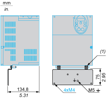


(1)
2 x M5 screws


Mounting and Clearance

Mounting Recommendations
Clearance

Depending on the conditions in which the drive is to be used, its installation will require certain precautions and the use of appropriate accessories.

Install the unit vertically:

  • Do not place it close to heating elements.

  • Leave sufficient free space to ensure that the air required for cooling purposes can circulate from bottom to the top of the unit.
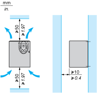


Mounting Types

Type A mounting


Type B mounting


Type C mounting
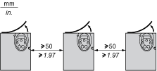


By removing the protective blanking cover from the top of the drive, the degree of protection for the drive becomes IP21. The protective blanking cover may vary according to the drive model, see opposite.


Specific Recommendations for Mounting in an Enclosure

To help ensure proper air circulation in the drive:

  • Fit ventilation grilles.

  • Check that there is sufficient ventilation. If there is not, install a forced ventilation unit with a filter. The openings and/or fans must provide a flow rate at least equal to that of the drive fans (refer to the product characteristics).

  • Use special filters with UL Type 12/IP54 protection.

  • Remove the blanking cover from the top of the drive.

Sealed Metal Enclosure (IP54 Degree of Protection)

The drive must be mounted in a dust and damp proof enclosure in certain environmental conditions, such as dust, corrosive gases, high humidity with risk of condensation and dripping water, splashing liquid, etc.This enables the drive to be used in an enclosure where the maximum internal temperature reaches 50°C.


Connections and Schema

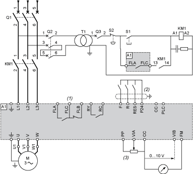
Recommended Wiring Diagram
3-Phase Power Supply


A1:
ATV 212 drive
KM1:
Contactor
Q1:
Circuit breaker
Q2:
GV2 L rated at twice the nominal primary current of T1
Q3:
GB2CB05
S1, S2:
XB4 B or XB5 A pushbuttons
T1:
100 VA transformer 220 V secondary
(1)
Fault relay contacts for remote signalling of the drive status
(2)
Connection of the common for the logic inputs depends on the positioning of the switch (Source, PLC, Sink)
(3)
Reference potentiometer SZ1RV1202

NOTE: All terminals are located at the bottom of the drive. Install interference suppressors on all inductive circuits near the drive or connected on the same circuit, such as relays, contactors, solenoid valves, fluorescent lighting, etc.

Switches (Factory Settings)

Voltage/current selection for analog I/O (VIA and VIB)


Voltage/current selection for analog I/O (FM)


Selection of logic type


(1)
negative logic
(2)
positive logic


Other Possible Wiring Diagrams
Logic Inputs According to the Position of the Logic Type Switch

“Source” position


“Sink” position


“PLC” position with PLC transistor outputs


(1)
PLC


(1)
PLC

2-wire control


F:
Forward
R:
Preset speed
(2)
ATV 212 control terminals

3-wire control


F:
Forward
R:
Stop
RES:
Reverse
(2)
ATV 212 control terminals

PTC probe


(2)
ATV 212 control terminals
(3)
Motor
Analog Inputs

Voltage analog inputs

External +10 V


(2)
ATV 212 control terminals
(4)
Speed reference potentiometer 2.2 to 10 kΩ


(2)
ATV 212 control terminals

Analog input configured for current: 0-20 mA, 4-20 mA, X-Y mA


(2)
ATV 212 control terminals
(5)
Source 0-20 mA, 4-20 mA, X-Y mA

Analog input VIA configured as positive logic input (“Source” position)


(2)
ATV 212 control terminals

Analog input VIA configured as negative logic input (“Sink” position)


(2)
ATV 212 control terminals


Performance Curves

Derating Curves

The derating curves for the drive nominal current (In) depend on the temperature, the switching frequency and the mounting type (A, B or C).

For intermediate temperatures (45°C for example), interpolate between 2 curves.
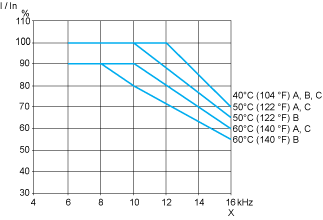


X
Switching frequency


© 2018 Switchboard in a Box. All Rights Reserved. Design & Developed by Shaligram Infotech